NVDLA 是英伟达于2017年开源出来的深度学习加速器框架。可惜的是,这个项目被开源出来一年后就草草停止维护了。
笔者本科的毕业设计为了与实验室研究的方向贴合,把NVDLA的RTL映射到了 Xilinx FPGA 上,并且上板编译了 Runtime 。映射成功后,很多伙伴对上板的过程很感兴趣,而这个步骤亦不是使用聊天软件说两句就可以概述的。于是写下这篇文章,记述Mapping 到 FPGA 过程中踩过的一些坑。
本设计的Github Repo地址:https://github.com/LeiWang1999/ZYNQ-NVDLA
你可以在这里看到我的本科毕业设计论文:Graduation Paper
开发器件:Zynq 7000+ / Zynq MPSoc
软件环境:
Ubuntu 18.04
Vivado 2019.1
Petalinux 2019.1
1. 硬件系统设计概述 本文采用的硬件版本是hw仓库 的master分支,v1的spec文件仅提供了full版本,应该没有FPGA能够塞得下。master 分支提供了 small 和 large 两个版本的spec 文件,我们使用 small 的配置,当然这个过程对 large 也是适用的,接下来首先讲一下如何生成rtl。
1.1 RTL 生成 如果你会chisel,还可以弯道超车,参考画面大佬的soDLA 项目,也能生成NVDLA的RTL代码。
如果使用官方的仓库生成RTL,我们需要给把官方的 tmake 搭建出来,这个过程中需要安装很多环境,例如 python、Java、perl、verilator,在这里我们就不用污染自己的环境了,利用docker大法使用别人安装好的环境:
1 docker pull farhanaslam/nvdla
启动docker之后,使用 tmake 生成 RTL
1 2 3 4 5 6 7 8 9 10 11 12 13 14 15 16 17 18 19 20 21 22 23 24 25 26 27 28 29 30 root@1d0954a2d18b:/usr/local/nvdla/nvdla_hwin spec/defs in spec/manual in spec/odif in vmod/vlibs in vmod/include in vmod/rams/model in vmod/rams/synth in vmod/rams/fpga/model in vmod/fifos in vmod/nvdla/apb2csb in vmod/nvdla/cdma in vmod/nvdla/cbuf in vmod/nvdla/csc in vmod/nvdla/cmac in vmod/nvdla/cacc in vmod/nvdla/sdp in vmod/nvdla/pdp in vmod/nvdla/cfgrom in vmod/nvdla/cdp in vmod/nvdla/bdma in vmod/nvdla/rubik in vmod/nvdla/car in vmod/nvdla/glb in vmod/nvdla/csb_master in vmod/nvdla/nocif in vmod/nvdla/retiming in vmod/nvdla/top
输出的RTL文件会在 out\nv_small\vmod里,但是如果直接在Vivado里引入vmod文件夹会导致LUT资源占用提高十倍左右,因为其内部的RAM在FPGA上会被映射到 LUT 去实现,所以我们需要替换成BRAM。
一个思路是把BRAM都替换成Vivado内部的Bram Controller,但是RAM文件的数量实在太多了。替换成BRAM其实有个简单的方式,就是使用rams\fpga这个文件夹里面的文件,为了图方便,我们将rams\synth删除,之后再把vmod文件夹全部添加到Vivado工程内部即可。
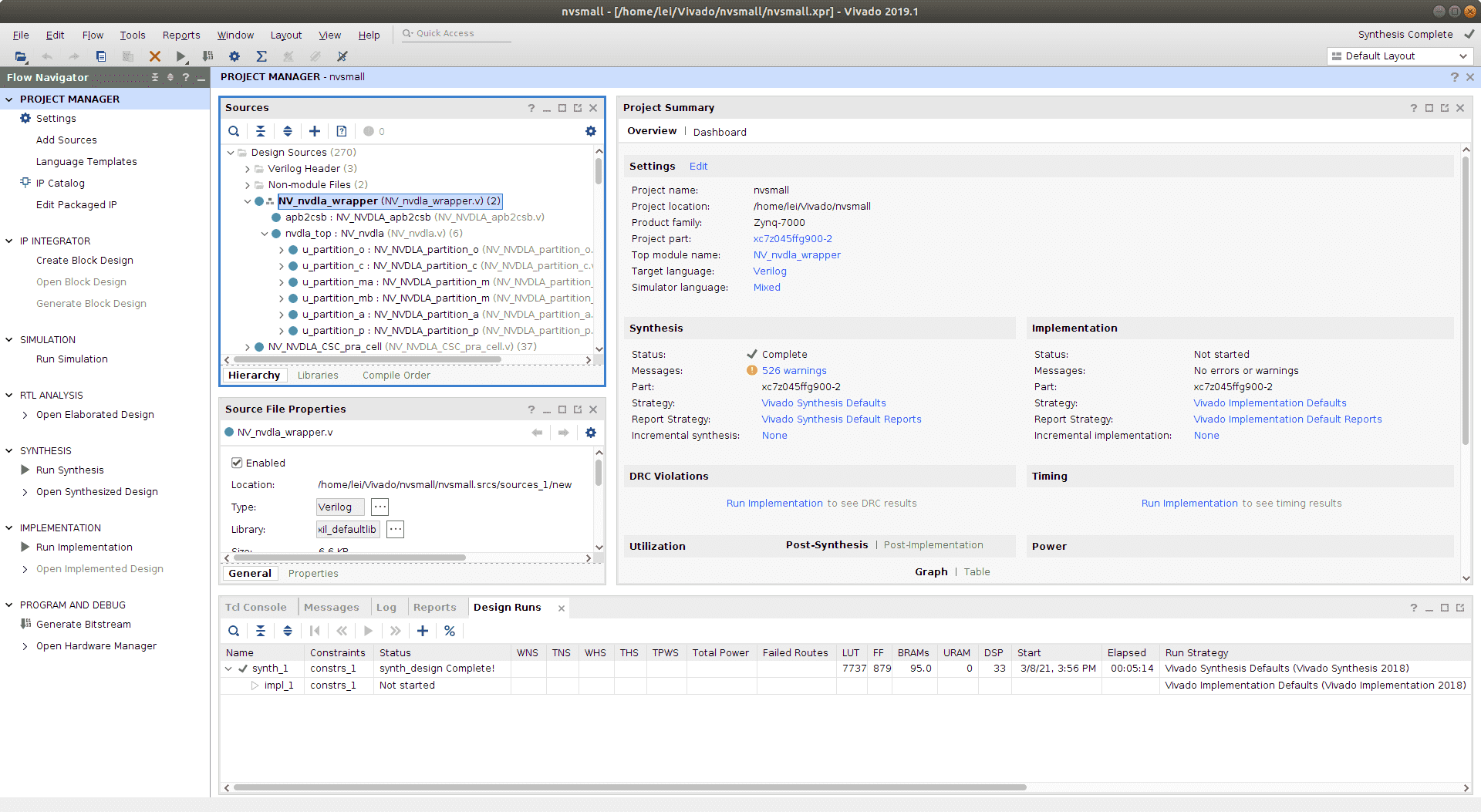
1.2 IP Package 在 Vivado 内部把删除过rams\synth文件夹之后的的vmod文件夹添加进来,NV_nvdla.v是NVDLA的Top文件,但是在项目里我们不着急把它设置为TOP,为了上板还要再做一层包装。
1.2.1 csb2apb 虽说NVDLA的控制总线协议是CSB,但是学习CSB协议有些麻烦,甚至在读写的时候需要做地址偏移压缩指令空间。在vmod里面官方给了一个电路,csb2apb。可以把csb总线换转为apb总线,这样在Vivado中设计会更加方便。
我们应该新建一个wrapper文件,其例化两者:
Top层的RTL代码内容如下:
1
2
3
4
5
6
7
8
9
10
11
12
13
14
15
16
17
18
19
20
21
22
23
24
25
26
27
28
29
30
31
32
33
34
35
36
37
38
39
40
41
42
43
44
45
46
47
48
49
50
51
52
53
54
55
56
57
58
59
60
61
62
63
64
65
66
67
68
69
70
71
72
73
74
75
76
77
78
79
80
81
82
83
84
85
86
87
88
89
90
91
92
93
94
95
96
97
98
99
100
101
102
103
104
105
106
107
108
109
110
111
112
113
114
115
116
117
118
119
120
121
122
123
124
125
126
127
128
129
130
131
132
133
134
135
136
137
138
139
140
141
142
143
144
145
146
147
148
149
150
151
152
153
154
155
156
157
158
159
160
161
162
module NV_nvdla_wrapper(input core_clk,input csb_clk,input rstn,input csb_rstn,output dla_intr,output nvdla_core2dbb_aw_awvalid,input nvdla_core2dbb_aw_awready,output [7 :0 ] nvdla_core2dbb_aw_awid,output [3 :0 ] nvdla_core2dbb_aw_awlen,output [2 :0 ] nvdla_core2dbb_aw_awsize,output [64 -1 :0 ] nvdla_core2dbb_aw_awaddr,output nvdla_core2dbb_w_wvalid,input nvdla_core2dbb_w_wready,output [64 -1 :0 ] nvdla_core2dbb_w_wdata,output [64 /8 -1 :0 ] nvdla_core2dbb_w_wstrb,output nvdla_core2dbb_w_wlast,output nvdla_core2dbb_ar_arvalid,input nvdla_core2dbb_ar_arready,output [7 :0 ] nvdla_core2dbb_ar_arid,output [3 :0 ] nvdla_core2dbb_ar_arlen,output [2 :0 ] nvdla_core2dbb_ar_arsize,output [64 -1 :0 ] nvdla_core2dbb_ar_araddr,input nvdla_core2dbb_b_bvalid,output nvdla_core2dbb_b_bready,input [7 :0 ] nvdla_core2dbb_b_bid,input nvdla_core2dbb_r_rvalid,output nvdla_core2dbb_r_rready,input [7 :0 ] nvdla_core2dbb_r_rid,input nvdla_core2dbb_r_rlast,input [64 -1 :0 ] nvdla_core2dbb_r_rdata,output [1 :0 ] m_axi_awburst,output m_axi_awlock, output [3 :0 ] m_axi_awcache,output [2 :0 ] m_axi_awprot, output [3 :0 ] m_axi_awqos, output m_axi_awuser, output m_axi_wuser, input [1 :0 ] m_axi_bresp,input m_axi_buser,output [1 :0 ] m_axi_arburst,output m_axi_arlock, output [3 :0 ] m_axi_arcache,output [2 :0 ] m_axi_arprot, output [3 :0 ] m_axi_arqos, output m_axi_aruser, input [1 :0 ] m_axi_rresp,input m_axi_ruser,input psel,input penable,input pwrite,input [31 :0 ] paddr,input [31 :0 ] pwdata,output [31 :0 ] prdata,output pready,output pslverrwire m_csb2nvdla_valid;wire m_csb2nvdla_ready;wire [15 :0 ] m_csb2nvdla_addr;wire [31 :0 ] m_csb2nvdla_wdat;wire m_csb2nvdla_write;wire m_csb2nvdla_nposted;wire m_nvdla2csb_valid;wire [31 :0 ] m_nvdla2csb_data;.pclk (csb_clk).prstn (csb_rstn).csb2nvdla_ready (m_csb2nvdla_ready).nvdla2csb_data (m_nvdla2csb_data).nvdla2csb_valid (m_nvdla2csb_valid).paddr (paddr).penable (penable).psel (psel).pwdata (pwdata).pwrite (pwrite).csb2nvdla_addr (m_csb2nvdla_addr).csb2nvdla_nposted (m_csb2nvdla_nposted).csb2nvdla_valid (m_csb2nvdla_valid).csb2nvdla_wdat (m_csb2nvdla_wdat).csb2nvdla_write (m_csb2nvdla_write).prdata (prdata).pready (pready).dla_core_clk (core_clk).dla_csb_clk (csb_clk).global_clk_ovr_on (1'b0 ).tmc2slcg_disable_clock_gating (1'b0 ).dla_reset_rstn (rstn).direct_reset_ (1'b1 ).test_mode (1'b0 ).csb2nvdla_valid (m_csb2nvdla_valid).csb2nvdla_ready (m_csb2nvdla_ready).csb2nvdla_addr (m_csb2nvdla_addr).csb2nvdla_wdat (m_csb2nvdla_wdat).csb2nvdla_write (m_csb2nvdla_write).csb2nvdla_nposted (m_csb2nvdla_nposted).nvdla2csb_valid (m_nvdla2csb_valid).nvdla2csb_data (m_nvdla2csb_data).nvdla2csb_wr_complete () .nvdla_core2dbb_aw_awvalid (nvdla_core2dbb_aw_awvalid).nvdla_core2dbb_aw_awready (nvdla_core2dbb_aw_awready).nvdla_core2dbb_aw_awaddr (nvdla_core2dbb_aw_awaddr).nvdla_core2dbb_aw_awid (nvdla_core2dbb_aw_awid).nvdla_core2dbb_aw_awlen (nvdla_core2dbb_aw_awlen).nvdla_core2dbb_w_wvalid (nvdla_core2dbb_w_wvalid).nvdla_core2dbb_w_wready (nvdla_core2dbb_w_wready).nvdla_core2dbb_w_wdata (nvdla_core2dbb_w_wdata).nvdla_core2dbb_w_wstrb (nvdla_core2dbb_w_wstrb).nvdla_core2dbb_w_wlast (nvdla_core2dbb_w_wlast).nvdla_core2dbb_b_bvalid (nvdla_core2dbb_b_bvalid).nvdla_core2dbb_b_bready (nvdla_core2dbb_b_bready).nvdla_core2dbb_b_bid (nvdla_core2dbb_b_bid).nvdla_core2dbb_ar_arvalid (nvdla_core2dbb_ar_arvalid).nvdla_core2dbb_ar_arready (nvdla_core2dbb_ar_arready).nvdla_core2dbb_ar_araddr (nvdla_core2dbb_ar_araddr).nvdla_core2dbb_ar_arid (nvdla_core2dbb_ar_arid).nvdla_core2dbb_ar_arlen (nvdla_core2dbb_ar_arlen).nvdla_core2dbb_r_rvalid (nvdla_core2dbb_r_rvalid).nvdla_core2dbb_r_rready (nvdla_core2dbb_r_rready).nvdla_core2dbb_r_rid (nvdla_core2dbb_r_rid).nvdla_core2dbb_r_rlast (nvdla_core2dbb_r_rlast).nvdla_core2dbb_r_rdata (nvdla_core2dbb_r_rdata).dla_intr (dla_intr).nvdla_pwrbus_ram_c_pd (32'b0 ).nvdla_pwrbus_ram_ma_pd (32'b0 ).nvdla_pwrbus_ram_mb_pd (32'b0 ).nvdla_pwrbus_ram_p_pd (32'b0 ).nvdla_pwrbus_ram_o_pd (32'b0 ).nvdla_pwrbus_ram_a_pd (32'b0 )assign nvdla_core2dbb_aw_awsize = 3'b011 ;assign nvdla_core2dbb_ar_arsize = 3'b011 ;assign m_axi_awburst = 2'b01 ;assign m_axi_awlock = 1'b0 ;assign m_axi_awcache = 4'b0010 ;assign m_axi_awprot = 3'h0 ;assign m_axi_awqos = 4'h0 ;assign m_axi_awuser = 'b1 ;assign m_axi_wuser = 'b0 ;assign m_axi_arburst = 2'b01 ;assign m_axi_arlock = 1'b0 ;assign m_axi_arcache = 4'b0010 ;assign m_axi_arprot = 3'h0 ;assign m_axi_arqos = 4'h0 ;assign m_axi_aruser = 'b1 ;assign pslverr = 1'b0 ;endmodule
封装好的RTL程序我也放在了仓库里的RTL目录下了,这里多加了一些总线的协议线是为了和AXI总线协议对齐,你可以和我一样把这些信号添加进去,但其实不写也没关系。等会儿Package IP的时候需要隐射成AXI接口。
1.2.2 关闭 Clock Gating NVDLA是面向ASIC设计,内部的RAM默认有clock gating用来降低功耗,但是FPGA的时钟树是设计好的,不需要这个,否则可能会因为clock buf资源不够导致布线过不去,打开 Settings|General|Language Options|Verilog Options,添加如下几个Global Define,关闭不必要的电路:
VLIB_BYPASS_POWER_CG
NV_FPGA_FIFOGEN
FIFOGEN_MASTER_CLK_GATING_DISABLED
FPGA
SYNTHESIS
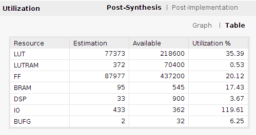
我们可以先综合一下,看看资源消耗情况。对于small配置,大概消耗了八万个LUT:
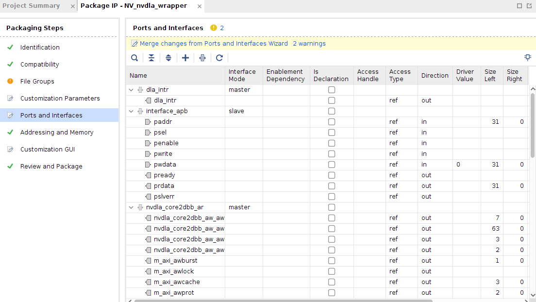
1.2.3 IP Package 接下来打开Package IP,进入Tools|Create and Package New IP|Package your current project在Ports and Inference页面,把APB、AXI4两个总线协议包装一下,这里可以让Vivado自动推导。
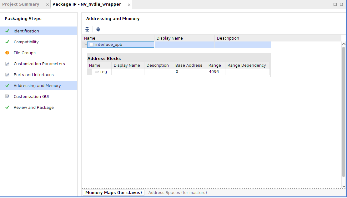
之后还要做Memory Map,APB的memory block要自行添加,不像AXI会自己分配。如果我们不添加memory block,则在Block Design里没办法给APB自动分配地址,在Addressing and Memory里,选择我们刚刚包装好的APB总线,右击选择Add Address Block,默认添加一个块就行了。
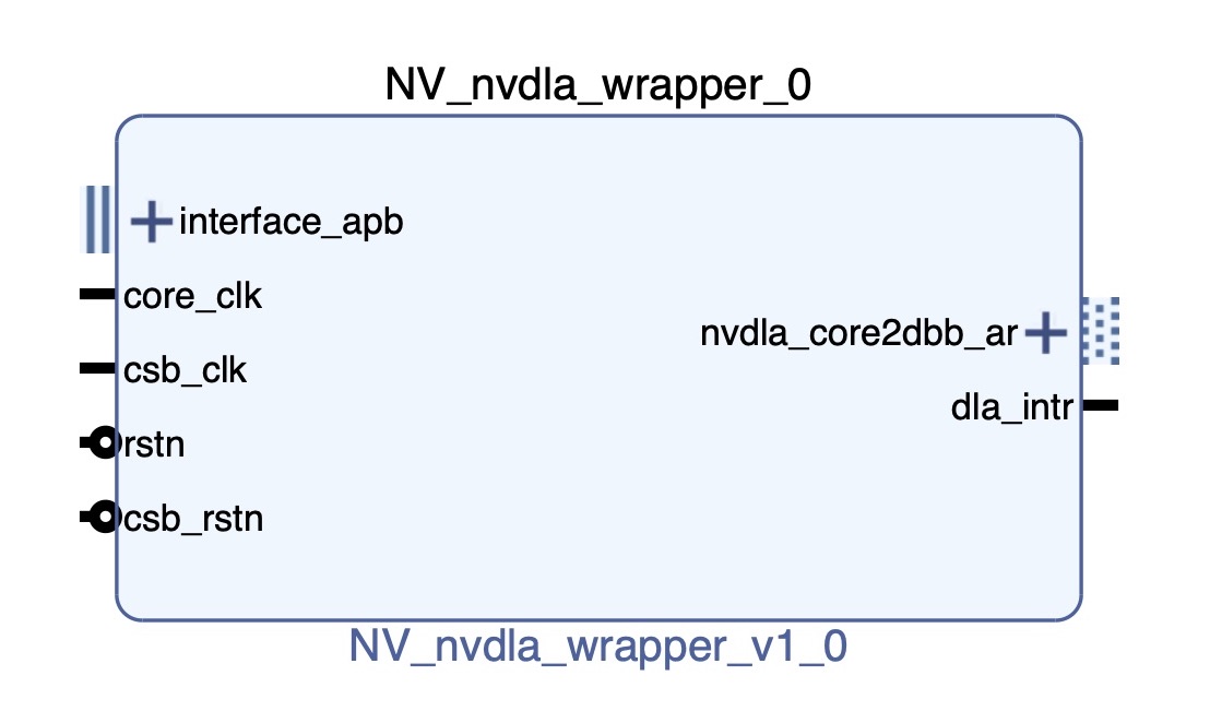
最后打包出来的IP如下图:
1.3 Block Design 在Vivado里面新建Block Design,这样连线:
AXI APB Bridge可以把APB总线协议转化为AXI总线协议,这样方便我们使用Vivado内部的Connect IP自动做内存映射。
Axi Smart Connect的作用是用来自动配置AXI设备的内存映射,与Axi InterConnect的作用是一样的,但是Smart更紧密的嵌入到了Vivado内部,不需要用户太多的干涉。在本设计中用到了两个SmartConnect、其中一个是将ZYNQ的AXI Master接入了NVDLA的控制总线,这样可以通过内存映射机制读写NVDLA的寄存器,另一个SmartConnect将DLA的主内存接口接入了ZYNQ的AXI Slave,这样就可以NVDLA就可以访问挂在在ARM侧的DDR存储,与处理器共用内存,这样处理器可以通过硬件DMA搬移数据,加快访存速度。
有关ZYNQ的配置,我分配到的资源有:
以太网,用来远程开发调试。
SD卡,用来存放BOOT、文件系统
UART,用来实现串口终端
FCLK_CLK0,我给了默认的100Mhz,用来给csb时钟,控制总线占用的时间不长不需要太快的速度。根据前人所述,core时钟在ASIC仿真下可以运行到1Ghz,但在FPGA设计里,我只给了100Mhz作为输入(能给200Mhz就不错了,笔者之前尝试过给500Mhz,会在寄存器读写的时候卡住,具体的最大频率的得出详见毕业论文)。
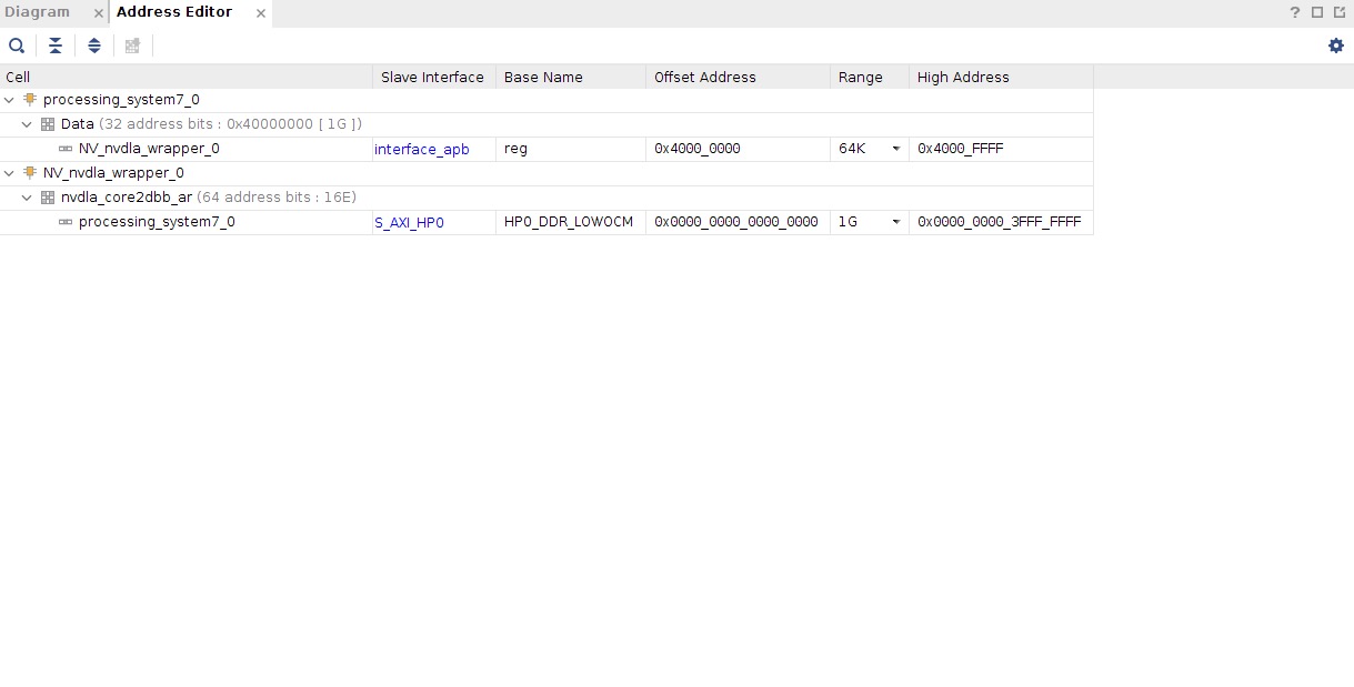
最后给大家看一下我的 Address Editor:
这样,我们在SDK里通过内存读写就能通过内存映射操作NVDLA的寄存器,例如读取NVDLA位于0x0000的寄存器值,我们只需要读入0x40000000上的数据即可,关于寄存器的地址与功能,详见官方提供的KMD代码中的opendla.h文件。
1.4 Generate Bit HDF 没有用到外部IO,可以不用编写XDC文件,直接一路Generate Bitstream生成bit。如果这个过程中没有报错,我们就可以Export Hardware到SDK内部了。
笔者因为用的第三方板卡,以太网的复位需要单独使用PL逻辑拉低,这里就不把Vivado工程Public出来误导大家了。
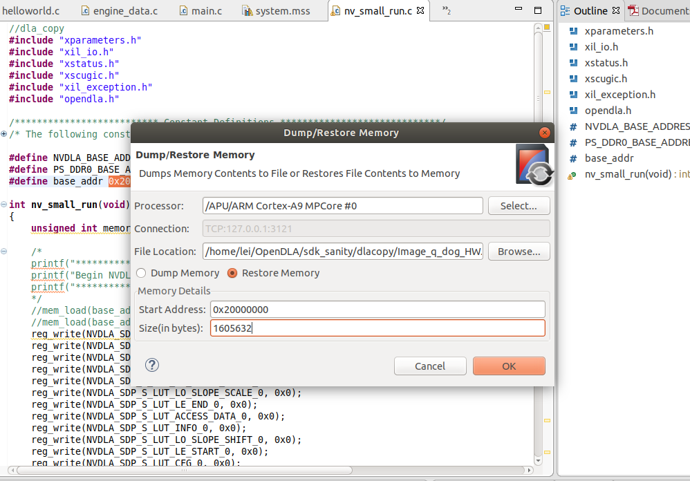
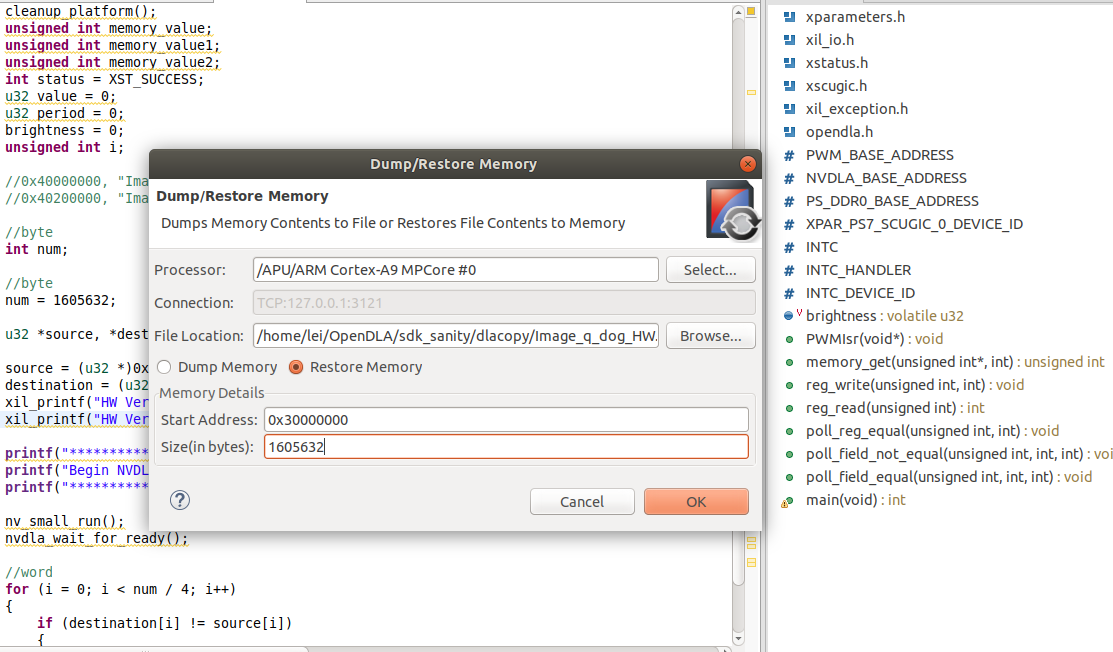
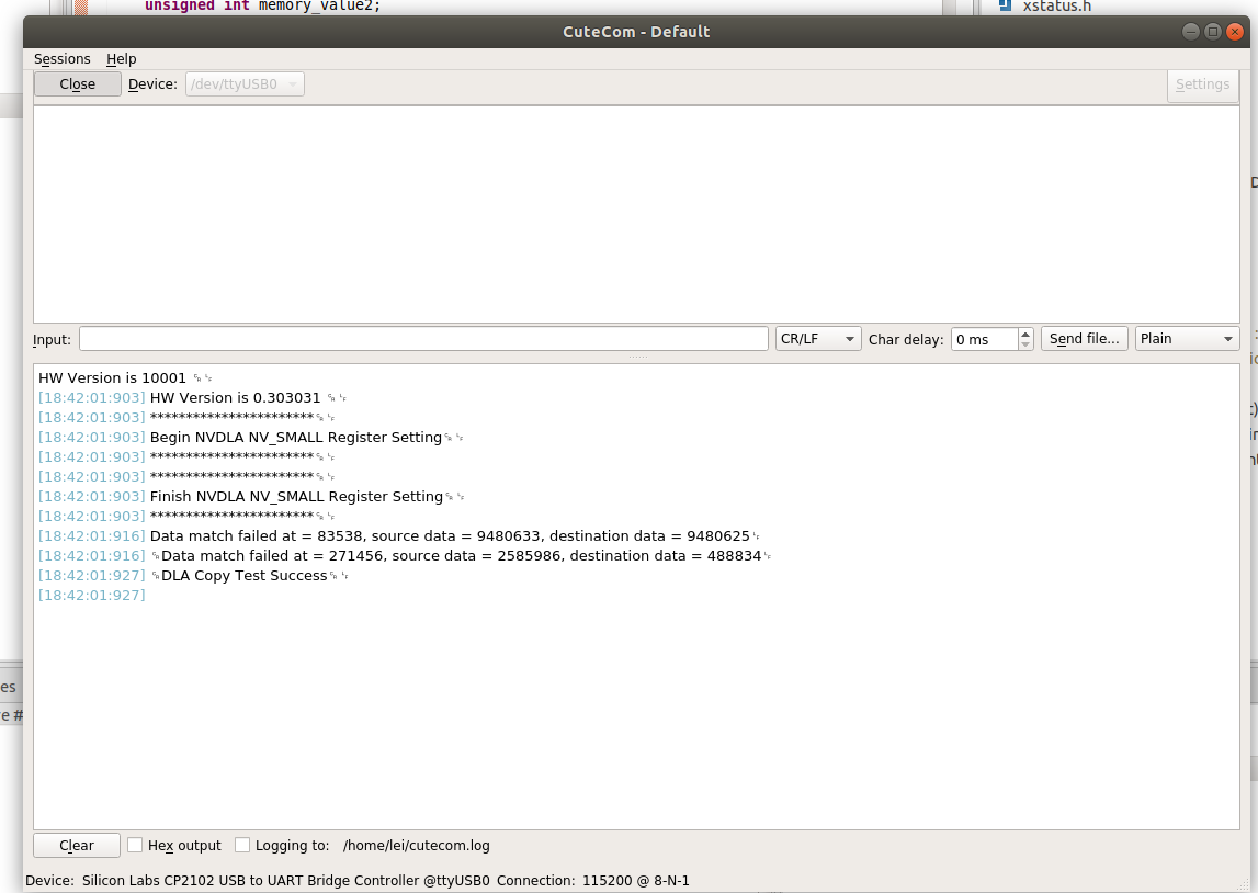
1.5 Sanity Test 这时候硬件栈就已经妥了,可能你还不放心是否NVDLA真的能够正常工作,这里可以用SDK跑一个Sanity试试,这个Sanity在Repo 的这个位置,能够使用SDP将内存上的一段数据搬移到另一段去。
在SDK打开Xilinx|Dump/Restore Memory,把测试案例和Golden数据放到对应的位置:
然后上板跑一下,在串口处观察是否work了:
你也可以在SDK上写一些别的Sanity,欢迎PR!
2. 软件系统设计概述 NVDLA的软件栈分为两个部分,一个是Compiler,Compiler在自己的主机上编译是与硬件无关的,而Runtime则需要调用KMD程序调度加速器,只能在板卡上运行。在这小节我们的目标是在ARM处理器上编译出Runtime,打通软件栈。
笔者在这个过程中踩了很多坑:
我们需要修改官方提供的KMD程序适配我们的内核版本与处理器。
需要修改device tree,覆盖NVDLA的compatible属性以适配加速器的驱动程序,并为加速器保留一段内存。
官方提供的SW项目不知道为什么只提供了libjpeg的链接库,明明这个源码是开源的,所以需要我们自己编译一下,而Patalinux本身没有包管理工具带来了种种不便,于是在这一章节,我将根文件系统替换为了Ubuntu 16.04。
small仅支持INT8推理,所以读取的loadable是需要结合TensorRT进行量化的,有关如何量化,参考我之前的博客:NVDLA量化笔记 。
2.1 Petalinux 相信能够调研NVDLA的伙伴一定不缺乏学习Petalinux的能力,所以这里就不讲了,这里只给几个Tips:
各个Petalinux版本之间的不同主要是使用的 Linux Kernel 版本不一样,这会导致KMD程序的几个函数会有不同,主要是DMA的。
最好,用的Xilinx套件的版本要统一,即使用Vivado 2019.1,也最好使用Petalinux 2019.1(有这个习惯主要是笔者还踩坑了自己构建PYNQ)。
其实Petalinux也可以用Docker大法,GitHub上有开源的Petalinux-Docker构建脚本。
假设,你已经安装好了Petalinux,接下来开始构建Linux,挂载加速器的旅程吧,这里提一嘴笔者使用的是Petalinux2019.1,对应的Linux Kernel版本为4.19:
2.1.1 create project 1 2 3 (petalinux) lei@lei-HP-EliteDesk-880-G1-TWR:~/petalinux-project$ petalinux-create -t project --template zynq -n smalldlain /home/lei/petalinux-project/smalldla
对于template,如果使用zynq-7000系列芯片,选择zynq,如果是zynq +UltraScale MPSoC,则选择zynqMP。
2.1.2 SDCard Boot 之后,将Vivado export hardware输出的.hdf文件拷贝到新建的petalinux工程目录下:
1 2 (petalinux) lei@lei-HP-EliteDesk-880-G1-TWR:~/petalinux-project/smalldla$ cp /home/lei/Vivado/DLA/DLA.sdk/nvsmall_wrapper.hdf .
在Image Packaging Configuration|Root Filesystem Type,选中SD card,然后保存,退出,系统会编译一段时间。
修改此处后,linux根目录系统rootfs将配置到SD中,而非默认的raminitfs,后者是将根目录系统镜像在boot阶段加载到内存中,一旦裁剪的kernel较大(大概超过120M),那么系统boot不起来;
2.1.3 外挂文件系统 下一步,裁剪kernel:
1 petalinux-config -c kernel
General setup,取消Initial RAM filesystem and RAM disk support,退出,保存配置。
这样文件系统就需要从SD卡启动,另一方面这个选项强制使BOOT从存储的第二个分区寻找文件系统,这样方便我们把文件系统替换为Ubuntu,仅需要把所有文件拷贝到第二分区即可。
2.1.4 Build 完事之后在这里需要先Build一下,因为这样能够使我们看到工具自动生成的设备树,方便我们找到NVDLA的label,因为在之后我们需要覆盖掉其compatible属性,以及给他分配内存。
2.2 KMD程序移植 原版的KMD程序的组织结构不适合作为Petalinux的模块,我重新组织了一下,这部分放在Repo的这个地方 。
新建一个Petalinux的Module,这里注意一定不要漏掉--enable,否则build的时候不会把Module程序一起编译:
1 2 3 4 5 6 7 (petalinux) lei@lei-HP-EliteDesk-880-G1-TWR:~/petalinux-project/smalldla$ petalinux-create -t modules -n opendla --enable in /home/lei/petalinux-project/smalldla/project-spec/meta-user/recipes-modules/opendla
删除原有的opendla下的所有文件,然后把zynq 7000文件夹下的所有内容copy到project-spec/meta-user/recipes-modules/opendla/下。
1
2
(petalinux) lei@lei-HP-EliteDesk-880-G1-TWR:~/petalinux-project/smalldla$ rm -rf project-spec/meta-user/recipes-modules/opendla/*cp ~/OpenDLA/kmd/Zynq7000/* project-spec/meta-user/recipes-modules/opendla/
如果是用的64位的处理器,即MPSoc的伙伴,使用ZynqMPSoc文件夹,因为这里我没有实践所以代码没有改。你们可以参考Reference第一条的博客,如果有意愿的话,可以给项目提一个PR。
我提供的自己的文件夹具体改了哪些地方?
在nvdla_gem.c里面,修改了dma_declare_coherent_memory这个函数的内容,首先ZYNQ 7045的片上存储有限,根据issue,这里只需要分配256MB的空间即可,第一个0x30000000是物理地址、第二个0x30000000是虚拟地址,第三个0x10000000指的是大小,如果你使用的是Zynq MPSoc,可以自行把这三个值替换为:0x40000000,0x40000000,0x40000000。另外,在Petalinux2019.1的Kernel版本中,DMA_MEMORY_MAP这个标志已经被废弃了,删除即可:
1 2 3 4 5 6 7 8 9 10 11 12 13 14 dma = dma_declare_coherent_memory(drm->dev, 0xC0000000 , 0xC0000000 ,0x40000000 , DMA_MEMORY_MAP | DMA_MEMORY_EXCLUSIVE);if (!(dma & DMA_MEMORY_MAP)) {goto unref;0x30000000 , 0x30000000 ,0x10000000 , DMA_MEMORY_EXCLUSIVE);if (dma) {goto unref;
在opendla.h里,定义small的宏:
1 2 3 4 5 6 7 8 9 10 #ifndef __OPENDLA_H_ #define __OPENDLA_H_ #define DLA_2_CONFIG #ifdef DLA_2_CONFIG #include <opendla_small.h> #else #include <opendla_initial.h> #endif #endif
在Makefile里,要把所有的文件生成的链接库加上,这里可以在Petalinux UserGuide里找到,其实有一份中文手册,可以参考我的FPGA 这个项目。
修改opendla.bb,把项目的源文件添加进来,具体的细节可以看文件内容。
2.3 Device Tree 有关Linux设备树的详细内容,请参考这篇博客 。
打开project-spec/meta-user/recipes-bsp/device-tree/files/system-user.dtsi,修改成如下内容:
1 2 3 4 5 6 7 8 9 10 11 12 13 14 15 16 17 18 19 /include/ "system-conf.dtsi" "shared-dma-pool" ;"nvidia,nv_small" ;
有关reserved memory如何设置,需要参考Xilinx Wiki,这里对应的是上文中用DMA分配的大小。对于MPSOC,这里是64位,一个地址要用两个cell,略有不同。
NV_nvdla_wrapper_0,是在components/plnx_workspace/device-tree/device-tree/pl.dtsi里可以查看的label,这样可以完成属性的覆盖。
“nvidia,nv_small”,这个值不能乱给,不然设备树找不到对应的内核程序,这个值在kmd的nvdla_core_callbacks.c里可以找到,由于我们是small配置,所以设置为”nvidia,nv_small”。
1 2 3 4 5 6 7 8 9 10 11 12 13 14 15 16 static const struct of_device_id nvdla_of_match [] ="nvidia,nvdla_os_initial" ,"nvidia,nv_small" ,"nvidia,nv_large" ,
如果用的是 ZYNQ MPSoc,那么设备树的内容如下:
1 2 3 4 5 6 7 8 9 10 11 12 13 14 15 16 17 18 /include/ "system-conf.dtsi" "nvidia,nv_small" ;
之后,重新build:
如果没有错误,接下来生成BOOT.BIN文件:
1 petalinux-package --boot --fsbl images/linux/zynq_fsbl.elf --fpga --u-boot --force
2.4 SD卡分区 准备一张8GB以上的SD卡,由于之前在Kernel配置了从SD卡启动,则这里我们要对SD卡分区,使用ubuntu自带的Disk工具就行。
对SD卡分两个区,第一个分区(如sdc1)的格式是FAT32,取名为BOOT、第二个分区(sdc2)的格式是EXT4,取名为ROOTFS,分区大小随意,BOOT分区可以小一点,ROOTFS分区可以大一点。注意,这里的分区必须严格是第一个和第二个区块,否则是BOOT不起来的。
把刚才生成的/images/linux/下BOOT.BIN, image.ub直接拷贝到SD卡的BOOT分区。
2.5 Ubuntu 16.04 根文件系统替换 前文提到了,Petalinux的使用体验极差,这里我们把根文件系统替换成Ubuntu 16.04。
笔者这里不详细阐述Why,但是会教你怎么做。
在FPGA 这个项目里,下载我准备好的ubuntu-16.04.2-minimal-armhf-2017-06-18根文件系统镜像,解压并且覆盖到SD卡里即可。
1 sudo tar xfvp armhf-rootfs-ubuntu-xenial.tar -C /media/lei/rootfs
但是,这样替换了rootfs之后,我们编译出来的opendla的modules并没有添加进来,打开petalinux文件夹下的\images\linux\rootfs.tar.gz,把里面的.\lib\modules解压出来,新增到ubuntu的\lib内部。
然后,把SD卡插到开发板上运行,测试一下insmod之后是否会多出中断信号和驱动。
1 2 3 4 5 6 7 8 9 10 11 12 13 14 15 16 17 18 19 20 21 22 23 24 25 26 27 28 29 30 31 32 root@arm:~
1
2
root@arm:~
这样,KMD就算是挂载成功了,接下来需要编译UMD。
UMD编译 为了方便,我们首先切换到Root用户:
使用apt来安装一些常用的包,比如ssh、make、curl什么的,如果不会用嵌入式板卡通过以太网来桥接上网,可以参考我以前的Blog 。
你可以使用官方的sw仓库里的umd文件夹,当然也可以是使用我的Repo里的UMD ,我自己改了几个地方:
在编译umd的时候,需要注意的是其有一个静态链接库libjpeg.a,需要我们自行编译,在编译的时候他会检测版本,原来官方用的版本是libjpeg6,我自行编译了libjpeg9,因为6的编译有点繁琐,并且改成9之后需要改一下头文件external\include\jconfig.h里的定义,将JPEG_LIB_VERSION的Value替换成90。
原本的umd,跑runtime读取jpeg图像的时候会有个RGB2BGR转换的操作,这会导致运行过程中libjpeg库会出现一个error,我给注释掉了,测试了N张图对结果的影响不大(我大概测试了几张图,结果的概率分布都没有影响,可能都量化到INT8就不在乎这点误差了)。
原本的umd程序的计算时间统计有问题。
然后,编译UMD:
1 2 3 cd ~/umdexport TOP=${PWD}
执行完该命令就会在out目录下面生成对应的可执行文件,直接执行会有这个Error:
1 2 root@arm:~/OpenDLA/umd/out/apps/runtime/nvdla_runtimewhile loading shared libraries: libnvdla_runtime.so: cannot open shared object file: No such file or directory
而这个链接库的地址在~/OpenDLA/umd/out/core/src/runtime/libnvdla_runtime/,这里有两种解决方法
export LD_LIBRARY_PATH=/root/OpenDLA/umd/out/core/src/runtime/libnvdla_runtime/
另一种,把libnvdla_runtime.so拷贝到nvdla_runtime的目录下即可
1 2 3 4 5 6 7 8 9 10 root@arm:~/OpenDLA/umd/out/apps/runtime/nvdla_runtimewhere options include:print this help messagetest in server modefor input imagefor input image
Well Done!
Runtime Test 这里,我们上板测试一下Runtime能否正常Work,首先,我们需要针对small配置利用Compiler得出Loadable。而由于small只支持int8,需要结合TensorRT做量化,这一个步骤有一万个坑,详细可以看我的前一篇博客:NVDLA INT8 量化笔记 。
在这里,笔者已经提供了三个测试网络与已经量化好的Loadable文件,详见这个Repo:
https://github.com/LeiWang1999/nvdla_loadables
在实际上板测试之前,可以先在vp的仿真环境下模拟Runtime,得到Golden数据作为对比。
跑个Lenet试试:
1 2 3 4 5 6 7 8 9 10 11 12 root@arm:~/OpenDLA/umd/out/apps/runtime/nvdla_runtime
跑个resnet18试试:
1 2 3 4 5 6 7 8 9 10 11 12 root@arm:~/OpenDLA/umd/out/apps/runtime/nvdla_runtime
这里会发现他的运行时间都是差不多的,实际上 resnet18 比 lenet5 要复杂许多,经过笔者研究,他还计算了一段 load 内存的时间,于是在最新版本的umd代码中,我将统计时间换算到发送给kmd,到kmd执行完毕。这样速度就正常一些了,截取一下文章里测到的数据:
但如果运行一个针对Imagenet的Resnet网络,会发现:
1 2 3 4 5 6 7 8 root@arm:~/OpenDLA/umd/out/apps/runtime/nvdla_runtimefunction loadMemory(), line 794)function load(), line 325)in RuntimeTest.cpp, function loadLoadable(), line 353)function run(), line 443)function launchTest(), line 87)
因为片上的内存不够而失败,PS侧的DDR只有1GB的空间,其中四分之一已经经保留给了NVDLA,仅剩700MB的空间,再想象一下ImageNet的网络确实很大,理所应当。
3. 结语 到这里,NVDLA的软件栈和硬件栈都Map到FPGA上了,NVDLA的坑很多,但很多前人都帮忙踩过了,本文的很多问题与解决方案,也是笔者总结NVDLA官方仓库的issue里的答案,感谢前人。
Reference
https://vvviy.github.io/2018/09/12/nv_small-FPGA-Mapping-Workflow-I/ https://vvviy.github.io/2018/09/17/nv_small-FPGA-Mapping-Workflow-II/ http://leiblog.wang/NVDLA-int8-%E9%87%8F%E5%8C%96%E7%AC%94%E8%AE%B0/ http://leiblog.wang/NVDLA-Parser-Loadable-Analysis/ http://nvdla.org/primer.html http://leiblog.wang/Embedding-board-internet-via-PC-Ethernet/ https://github.com/SameLight/ITRI-OpenDLA


Comments